
Bobble-Bot
A two-wheeled balancing robot, built so that students and hobbyists could play with feedback control on something real.
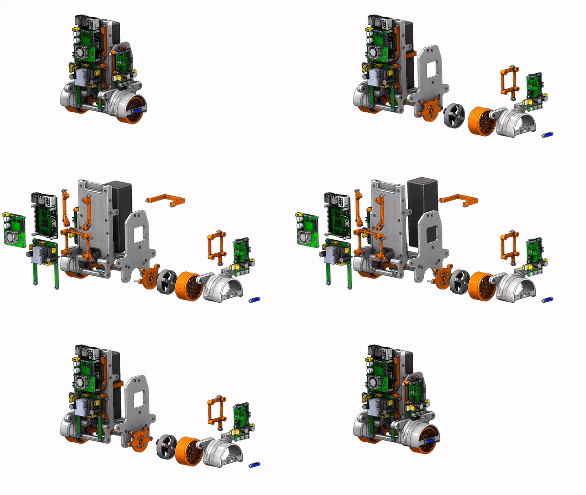
Bobble-Bot is a two-wheeled inverted pendulum. It is a classical problem in control theory, which is exactly why it makes a good teaching platform: the maths is in every textbook, and the robot falls over the moment you get it wrong.
I wrote the balance controller, the Gazebo simulation used to develop it, and the CAN bus drivers between the Raspberry Pi and the motor controller firmware. The controller runs in real time on the Pi. All of it is open source, because the point was for other people to be able to pick it up.
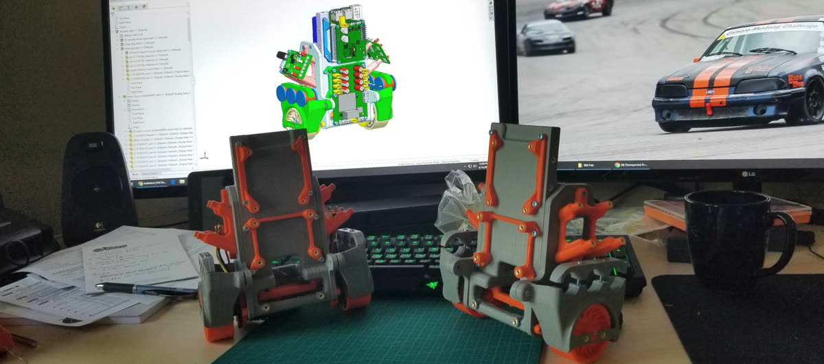
What I wrote about it
These are from 2018, moved here from the old site before that domain was reused. Oldest first, which is roughly the order the work happened in. The text is unchanged.
- 01Analyzing ROS data using Jupyter, part 124 Jan 2018
- 02Analyzing ROS data using Jupyter, part 224 Jan 2018
- 03Analyzing ROS data using Jupyter, part 324 Jan 2018
- 04Docker for Gazebo-ROS simulations26 Jan 2018
- 05Using simulation for testing and continuous integration20 May 2019
- 06Learn controls with Bobble-Bot, part 125 May 2019
- 07Using Matlab with Bobble-Bot30 Jun 2019
The controls post lost four figures with the old image host. Three are back: both halves of the equations of motion and the gain table come from my 2018 thesis defence, and the control-law diagram is redrawn from the cascade described in our IEEE paper. Each says so in its caption.
All seven are here. Four figures did not survive the move: three screenshots in the CI post and one still in the Matlab post. The CI post carries a marked plate where each one stood, so the gap is visible rather than silently papered over. The Matlab still was replaced with a recording of the same experiment, which says so in its caption.
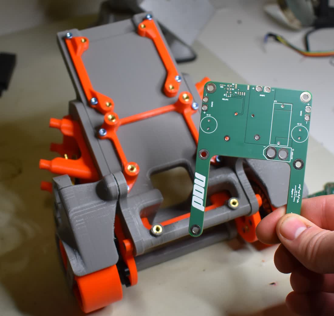
The bit that carried over
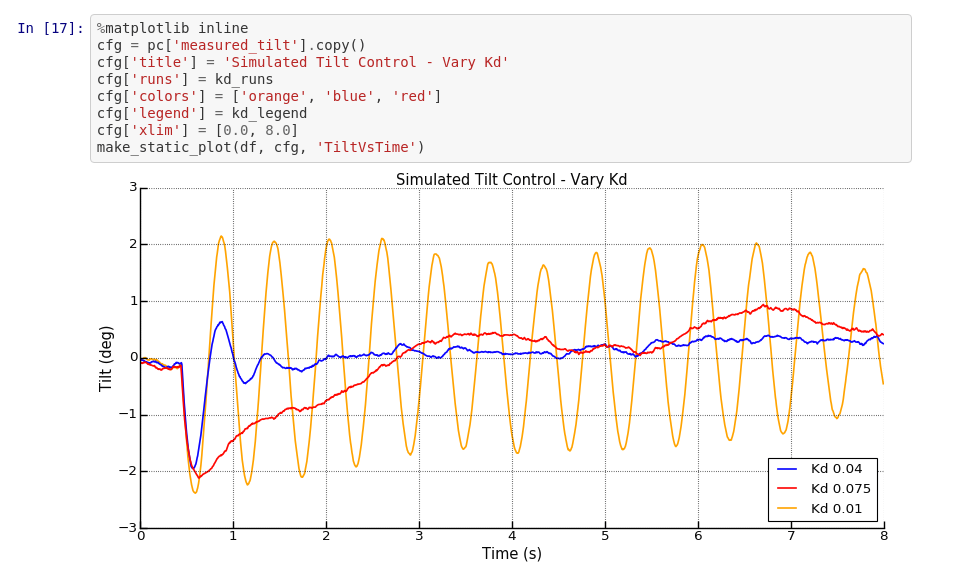
Two habits from Bobble-Bot are the reason the pendulum work looks the way it does. The first is developing against a simulation from day one, so that a change can be tested before it can break hardware. The second is treating the analysis as code — recorded runs into a notebook, plots regenerated from a script rather than screenshotted once and pasted somewhere.
There is a paper about the real-time control side, Real-Time Control of a Self-Balancing Robot Using ROS, if you want the more formal version.